Passive system for detecting and monitoring FPV drones and UAVs through radio-frequency signals. It scans analog video channels, analyzes signal strength, and generates alerts when a transmission is detected or lost.
An ESP32-based passive RF monitoring system designed to detect radio-frequency activity associated with FPV drones.
The project combines 5.8 GHz analog video detection using an RX5808 receiver with 2.4 GHz RF activity monitoring using an NRF24L01. The system analyzes signal strength, stability, persistence, and frequency activity to identify potential FPV video transmissions and FHSS-like radio activity.
Note: The 2.4 GHz detector identifies RF activity and frequency-hopping patterns compatible with FHSS. It does not uniquely or cryptographically identify ExpressLRS (ELRS).


- Assemble the hardware according to the wiring and pinout sections below.
- Install ESP32 board support in the Arduino IDE.
- Install the RF24 library using the Arduino Library Manager.
- Open the project firmware (
.ino) in the Arduino IDE. - Select the correct ESP32 board and serial port.
- Compile and upload the firmware.
- Open the Serial Monitor at 115200 baud.
- Power on the detector without a nearby FPV transmitter and allow the RSSI baseline calibration to complete.
- Power on an analog FPV transmitter and observe the video-monitor OLED, LEDs, and buzzer.
- Optionally connect the RX5808 VIDEO / AV output to a compatible composite monitor to view the received analog video in real time.
Important: Power the NRF24L01 from 3.3 V only. A 10–100 µF capacitor between VCC and GND is recommended for power stability.
The detector combines two independent passive RF monitoring paths:
                  Passive Drone Detection
                           │
             ┌─────────────┴─────────────┐
             │                           │
             ▼                           ▼
      ┌─────────────┐             ┌─────────────┐
      │   5.8 GHz   │             │   2.4 GHz   │
      │   RX5808    │             │  NRF24L01   │
      └──────┬──────┘             └──────┬──────┘
             │                           │
        FPV frequency                RF channel
          scanning                    scanning
             │                           │
        RSSI samples                  RPD energy
             │                           │
      Mean / StdDev /              Active channels
        persistence                + frequency spread
             │                           │
      Confidence score              FHSS-like pattern
             │                           │
             └─────────────┬─────────────┘
                           ▼
                     Detection logic
                           │
              ┌────────────┼────────────┐
              ▼            ▼            ▼
             OLED          LED        Buzzer
The RX5808 path scans analog FPV video frequencies and evaluates RSSI strength, stability, persistence, and confidence. The NRF24L01 path scans the 2.4 GHz band for distributed RF activity and frequency spread that may indicate an FHSS-like transmission.
Both paths are passive: the system observes existing RF activity and does not need to establish a communication link with the detected transmitter.
- Passive RF monitoring
- Analog FPV video detection
- 2.4 GHz RF activity monitoring
- Automatic scanning of 72 FPV frequencies
- RSSI signal analysis
- Mean and standard deviation calculation
- Dynamic detection thresholds
- Automatic RSSI noise-floor calibration
- Signal confidence score from 0 to 100
- Detection persistence analysis
- Signal lock/unlock hysteresis
- Channel and band change detection
- FHSS-compatible activity detection
- Two independent OLED displays
- LED status indicators
- Buzzer alerts
- Serial debugging at 115200 baud
| Component | Quantity | Purpose |
|---|---|---|
| ESP32 | 1 | Main processing unit |
| RX5808 | 1 | 5.8 GHz analog FPV receiver |
| NRF24L01 | 1 | 2.4 GHz RF activity detector |
| SSD1306 128×64 OLED | 2 | Real-time system information |
| Green LED | 1 | Calibration indicator |
| Red LED | 2 | Video and FHSS detection indicators |
| Buzzer | 1 | Audible detection alerts |
| 10–100 µF capacitor | 1 | NRF24L01 power stabilization |
| Wires / PCB / Breadboard | As required | Hardware assembly |
Click an image to open the corresponding component page.
 RX5808 |
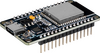 ESP32 |
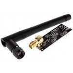 NRF24L01 |
 SSD1306 128×64 OLED |
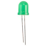 Green LED |
 Red LED |
 Buzzer |
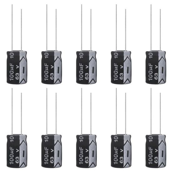 10–100 µF capacitor |
The following overview summarizes the main hardware connections. The detailed pinout tables are provided later in this README.
RX5808 DATA  ─────────────► GPIO 23
RX5808 CLK   ─────────────► GPIO 18
RX5808 CS    ─────────────► GPIO 5
RX5808 RSSI  ─────────────► GPIO 34

RX5808 VIDEO / AV OUT ────► Composite AV monitor / display (optional)
RX5808 GND            ────► AV monitor GND
NRF24L01 SCK   ───────────► GPIO 25
NRF24L01 MISO  ───────────► GPIO 19
NRF24L01 MOSI  ───────────► GPIO 26
NRF24L01 CE    ───────────► GPIO 27
NRF24L01 CSN   ───────────► GPIO 33
NRF24L01 VCC   ───────────► 3.3 V
NRF24L01 GND   ───────────► GND
          10–100 µF
3.3 V ──────||────── GND
       NRF24L01 supply
Warning: Do not power the NRF24L01 from 5 V. Use 3.3 V only.
Video OLED
SDA ──────────────────────► GPIO 21
SCL ──────────────────────► GPIO 22
I2C address ──────────────► 0x3C

2.4 GHz OLED
SDA ──────────────────────► GPIO 16
SCL ──────────────────────► GPIO 17
I2C address ──────────────► 0x3C
Green calibration LED ────► GPIO 12
Red video detection LED ──► GPIO 14
Red FHSS detection LED ───► GPIO 13
Buzzer ───────────────────► GPIO 15
The RX5808 subsystem scans common analog FPV video frequencies.
If the RX5808 module exposes its VIDEO / AV output, it can be connected directly to a compatible composite AV monitor or display to watch the received analog FPV video in real time.
RX5808 VIDEO / AV OUT  ─────►  Composite AV monitor / display
RX5808 GND             ─────►  AV monitor GND
This connection is optional and independent from the ESP32 detection logic. The ESP32 uses the RX5808 control and RSSI signals for scanning and detection, while the external AV display can be used to visually inspect the video signal on the currently tuned channel.
Note: The exact video-output pin name and pinout can vary between RX5808 boards or breakout modules. Verify the pinout of your specific module before connecting an AV display.
The firmware contains 9 FPV bands with 8 channels each, providing a total of:
9 × 8 = 72 frequencies
| Band |
|---|
| A |
| B |
| E |
| F |
| R |
| U |
| O |
| L |
| H |
The configured frequency range extends approximately from:
5325 MHz to 5945 MHz
For every scanned frequency, the ESP32 collects multiple RSSI samples from the RX5808.
The firmware calculates:
- Mean RSSI
- RSSI standard deviation
- Signal strength relative to the noise floor
- Signal persistence
- Detection confidence
The RX5808 RSSI output is connected to the ESP32 ADC and read with 12-bit resolution.
ADC Range: 0 – 4095
The system generates a confidence score between:
0 – 100
The score is calculated from three main factors:
| Parameter | Weight |
|---|---|
| Signal intensity | 50% |
| Signal stability | 30% |
| Persistence | 20% |
This helps reduce detections caused by short RF spikes or unstable interference.
The firmware can classify the strongest detected signal as:
VALID_VIDEO
NOISE/INTERFERENCE
STRONG_UNSTABLE
A valid video signal requires sufficient signal strength, stability, persistence, and confidence.
At startup, the system automatically measures the local RSSI noise floor.
The current firmware takes:
250 RSSI samples
From this baseline, dynamic thresholds are generated:
Detection ON  = Baseline + RSSI Margin
Detection OFF = Detection ON - Hysteresis
This allows the detector to adapt to different RF environments.
For better calibration, avoid operating a nearby FPV transmitter while the device is starting.
The second detection subsystem uses an NRF24L01 connected to the ESP32 through HSPI.
It scans NRF channels:
Channel 0 → Channel 83
Corresponding approximately to:
2400 MHz → 2483 MHz
The NRF24L01 uses its RPD (Received Power Detector) function to determine whether RF energy is present on each channel.
The firmware looks for:
- Multiple active channels
- Activity distributed across the spectrum
- Sufficient frequency spread
- Repeated detections over consecutive scans
These characteristics may indicate frequency-hopping spread spectrum (FHSS) activity.
The NRF24L01 detector does not decode ExpressLRS packets.
Detection is based only on RF energy distribution and hopping-like patterns.
Therefore:
FHSS detected ≠ ELRS confirmed
The OLED intentionally displays:
ELRS?
rather than claiming definitive ELRS identification.
Other 2.4 GHz transmitters may produce similar RF activity.
The project uses two SSD1306 128×64 OLED displays.
Both displays use I2C address:
0x3C
This is possible because the ESP32 uses two independent I2C controllers.
Displays:
- Detection status
- FPV band
- Channel
- Frequency
- Mean RSSI
- RSSI standard deviation
- Confidence score
- Signal classification
Example:
VIDEO MONITOR
Status: TARGET
B:R CH:4 5769MHz
mean:1450 sd:45
score:87
VALID_VIDEO
Displays:
- NRF24L01 status
- FHSS detection state
- Number of active channels
- Confirmation counter
- Detected frequency spread
Example:
2.4 GHz / FHSS
NRF24: OK
Pattern: ELRS?
hits:8 conf:3/3
2403-2478 MHz
FHSS inconclusive
| RX5808 | ESP32 |
|---|---|
| DATA | GPIO 23 |
| CLK | GPIO 18 |
| CS | GPIO 5 |
| RSSI | GPIO 34 |
| OLED | ESP32 |
|---|---|
| SDA | GPIO 21 |
| SCL | GPIO 22 |
| Address | 0x3C |
| OLED | ESP32 |
|---|---|
| SDA | GPIO 16 |
| SCL | GPIO 17 |
| Address | 0x3C |
| NRF24L01 | ESP32 |
|---|---|
| SCK | GPIO 25 |
| MISO | GPIO 19 |
| MOSI | GPIO 26 |
| CE | GPIO 27 |
| CSN | GPIO 33 |
| VCC | 3.3 V |
| GND | GND |
Do not power the NRF24L01 from 5 V. Use 3.3 V only.
A 10–100 µF capacitor between VCC and GND is recommended to improve power stability.
| Device | ESP32 GPIO |
|---|---|
| Green calibration LED | GPIO 12 |
| Red video detection LED | GPIO 14 |
| Red FHSS detection LED | GPIO 13 |
| Buzzer | GPIO 15 |
Blinks while the RSSI baseline is being calibrated.
Turns on when the system identifies a valid analog video target.
Turns on when a persistent FHSS-compatible RF pattern is detected.
The ESP32 generates the buzzer signal using PWM.
Configured tone:
2200 Hz
The buzzer provides audible feedback during events such as:
- Device startup
- Valid video detection
- FPV channel changes
- FPV band changes
The firmware is designed for the ESP32 Arduino framework.
#include <Arduino.h>
#include <Wire.h>
#include <SPI.h>
#include <RF24.h>
#include <math.h>
#include <string.h>
Most libraries are included with the ESP32 Arduino environment.
The main external dependency is:
Install the RF24 library using the Arduino IDE Library Manager.
Arduino IDE
   ↓
Sketch
   ↓
Include Library
   ↓
Manage Libraries
   ↓
Search: RF24
No external SSD1306 graphics library is required by the current firmware.
The project contains a minimal SSD1306 implementation directly in the source code, including:
- SSD1306 initialization
- Frame buffer handling
- Pixel drawing
- Text rendering
- 5×7 ASCII font
- I2C display updates
git clone https://github.com/Bit101-git/passive_drone_detection-PDD.gitOpen:
V1-analog_video_5.8Ghz.ino
with the Arduino IDE.
Make sure your Arduino IDE has ESP32 board support installed.
Install the RF24 library using the Arduino Library Manager.
Wire the components according to the pinout tables above.
Select the appropriate ESP32 board from the Arduino IDE.
Compile the firmware and upload it to the ESP32.
Set the baud rate to:
115200
The main detection parameters can be adjusted directly in the firmware.
SCAN_INTERVAL_MS
TUNE_SETTLE_MS

RSSI_CAL_SAMPLES
RSSI_WINDOW_SAMPLES

RSSI_MARGIN
RSSI_STDDEV_MAX
RSSI_HYST

VIDEO_PERSIST_N_DEFAULT

NRF_SCAN_INTERVAL_MS
NRF_FIRST_CHANNEL
NRF_LAST_CHANNEL

FHSS_MIN_HITS
FHSS_MIN_SPREAD
FHSS_CONFIRM_SCANS
FHSS_HOLD_MS
These parameters control the sensitivity, stability, persistence, and behavior of the detection algorithms.
Start
  ↓
RSSI Calibration
  ↓
Scan 72 FPV Frequencies
  ↓
Collect RSSI Samples
  ↓
Calculate Mean + Standard Deviation
  ↓
Select Strongest Frequency
  ↓
Compare Against Dynamic Threshold
  ↓
Calculate Persistence
  ↓
Calculate Confidence Score
  ↓
Classify Signal
  ↓
Display / LED / Buzzer
Start NRF24L01
  ↓
Scan Channels 0–83
  ↓
Test RPD Energy
  ↓
Count Active Channels
  ↓
Calculate Frequency Spread
  ↓
Check FHSS Pattern
  ↓
Confirm Across Multiple Scans
  ↓
Display / LED Alert
This project is designed as a passive detector.
It does not need to establish a communication link with the detected FPV system. Instead, it observes RF activity already present in the environment.
The RX5808 monitors analog FPV video transmissions while the NRF24L01 monitors energy patterns in the 2.4 GHz ISM band.
This project should not be considered a universal drone identification system.
Detection performance can be affected by:
- RF interference
- Wi-Fi networks
- Bluetooth devices
- Other 2.4 GHz transmitters
- Nearby analog video transmitters
- Antenna type and orientation
- Receiver sensitivity
- Distance from the transmitter
- Local electromagnetic noise
The NRF24L01 subsystem detects RF energy and FHSS-like patterns but cannot determine with certainty which protocol or device generated them.
Contributions are welcome.
You can contribute by:
- Reporting bugs
- Improving detection algorithms
- Testing different RF environments
- Improving documentation
- Adding hardware support
- Optimizing scan performance
- Improving the user interface
Feel free to open an Issue or submit a Pull Request.
This project is released under the MIT License.
You are free to use, modify, distribute, and improve the project according to the terms of the license.
See the LICENSE file for more information.
This project is intended for research, education, experimentation, and RF monitoring.
Users are responsible for ensuring that their use of the project complies with all applicable local laws and regulations.
The authors and contributors are not responsible for misuse of the software or hardware.
If you find this project useful, consider giving the repository a star ⭐.
Contributions, testing, documentation improvements, and feedback are welcome.