




A DIY, open-source, dual-universe DMX interface with an OLED menu, standalone CUE engine, and full galvanic isolation.
Lighting control hardware is often expensive and hard to customize. This project provides an affordable, reliable, and highly customizable dual-universe DMX interface using the Raspberry Pi Pico.
By emulating the industry-standard Enttec DMX USB Pro Mk2 protocol, the interface works out of the box with popular lighting software like QLC+ — no custom drivers required.
It also features a built-in OLED display, physical controls, and a standalone CUE engine for managing DMX setups directly from the device.
Why USB instead of ArtNet? My first prototype used ArtNet, but for my use cases it was far more convenient to connect via USB rather than dealing with LAN cables, IP addresses, and DHCP configuration.
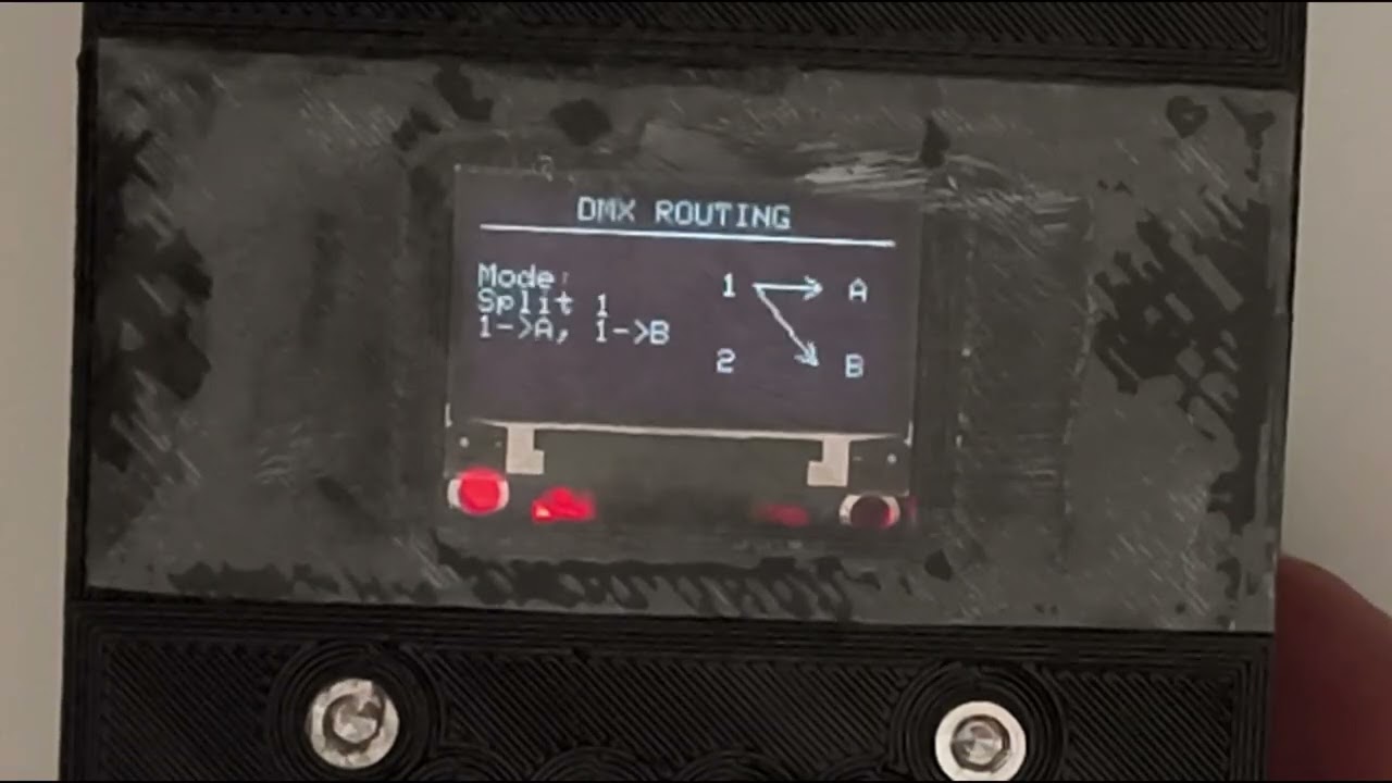
Menu navigation and node introduction:
| Feature | Description |
|---|---|
| 🔌 Enttec Pro Mk2 Emulation | Native compatibility with QLC+ and other major lighting software |
| 🎚️ Dual Universe Output | Two full DMX-512 universes via MAX485 transceivers |
| 🖥️ OLED Menu System | Integrated SSD1306 display + 4-button interface for on-device control |
| 💾 Standalone CUE Engine | Record and store up to 10 dual-universe CUEs to flash memory |
| 🔀 DMX Crossfading | Smooth transitions with configurable fade times |
| 🛣️ Advanced Routing | Flexible mapping of Universe 1/2 to physical Outputs A/B |
| 💿 Persistent Settings | All preferences saved to EEPROM |
Configurable fallback modes when USB connection is lost:
- ⬛ Blackout — all channels go to zero
- ⏸️ Hold Last Value — freeze the last DMX frame
- 🎬 Play CUE — automatically trigger a stored CUE
This project uses PlatformIO with the Arduino framework for the Raspberry Pi Pico (Earle Philhower core).
- Install Visual Studio Code and the PlatformIO IDE extension.
- Open this project folder in VSCode.
- Hold the BOOTSEL button on the Pico and plug it in via USB.
- Once the Pico mounts as a mass storage device, click Upload (→) in the PlatformIO toolbar.
- Build the project in PlatformIO (Build / ✓ icon).
- Find the generated
firmware.uf2in.pio/build/pico/. - Hold BOOTSEL and plug in the Pico — it appears as
RPI-RP2. - Drag and drop
firmware.uf2onto the drive. The Pico reboots automatically.
The circuit implements full galvanic isolation between the USB controller and the DMX transceiver to protect the host computer from electrical faults, ground loops, and high-voltage transients.
An isolated DC-DC converter (B0505S-1W) supplies a dedicated floating 5 V rail, and two high-speed 6N137 optocouplers isolate the logic signals driving the MAX485.
| # | Component | Link |
|---|---|---|
| 1 | Raspberry Pi Pico (RP2040) | AliExpress |
| 2 | MAX485 Transceiver Module ×2 | AliExpress |
| 3 | XLR 3-Pin Female Panel Connector ×2 | AliExpress |
| 4 | 6N137 High-Speed Optocoupler ×2 | AliExpress |
| 5 | B0505S-1W Isolated DC-DC Converter | AliExpress |
| 6 | Perfboard / PCB | AliExpress |
| 7 | Tactile Push Buttons ×4 | AliExpress |
| 8 | SSD1306 0.96″ OLED Display | AliExpress |
| 9 | Assorted Resistors | — |
| 10 | 3D Printed Case (optional) | See below |
Note
This diagram was drawn after the build, so minor inaccuracies are possible — but it should be correct.

The enclosure is composed of 3 parts and uses M3 screws for assembly:
| Part | File |
|---|---|
| Case | Case.stl |
| Top Panel | Top Panel.stl |
| USB Panel | USB Panel.stl |
Important
The USB hole position must be aligned with the RP2040 on the PCB. If you use the same perfboard and place the Pico board flush against the edge, the hole should match.
In QLC+, select Pro Mk2 in the mode menu:

- The OLED screen brightness is not sufficient in direct daylight.
Click to expand build photos
The two opto-isolators (6N137) with their associated pull-up resistors.

The RP2040 on the right, MAX485 modules and B0505S on the bottom-left. Black connectors carry the OLED and button signals from the top panel.

This project is licensed under the Creative Commons BY-NC-SA 4.0 license.